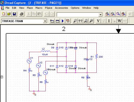
Pspice Schematic 16.5
Include OrCad Capture for schematic design, various librarian tools, OrCad PCB editor for place and route, Pspice® a/d for circuit simulation, OrCad PCB si for signal integrity analysis, and sPeCCTra® for OrCad for automatic routing. Easy to use and intuitive, these tools represent. I am working on a circuit simulation in pspice, I have the free lite version (16.5) and I am having a lot of trouble with the transformers. I am trying to use a transformer with a 30:1 turns ratio but the only transformer in the pspice library that actually will successfully run a simulation is the linear transformer and I can't seem to change the turns ratio. Sensitivity and Monte Carlo analysis require tolerances assigned to the value of the components in your design. Applying a global device tolerance will apply the tolerance to all instances of a resistor, capacitor, inductor, voltage source, or current source. Sampling of notations that PSPICE recognizes. PSpice Notation PSpice Notation 103 K E3 10-3 m E-3 106 Meg (not M) E6 10-6 u E-6 109 G E9 10-9 n E-9 10-12 p (pico) E-12 10-15 f (femto) E-15 Your schematic is now complete! Save your schematic - -From the main menu: File-Save. 1 Place part icon. Add Library icon. Creating the design of a circuit with PSpice Schematics, the project will be composed of a schematic file.SCH, a control file.CIR and a circuit description file.NET both automatically generated from Schematics, and files.INC containing subcircuits, to be included in the project.
| Fig: Cadence Orcad 16.5 Free Download |
 is an integrated tool for schematic design entry, circuit board design, simulation and pcb layout board design software for designing electronics products. It is used by professional engineers and circuit board designer around the world for schematics drawing of electronics circuit board and for PCB board Prototyping.
The design step to design PCB board is to enter the electronics schematics, then to perform simulation and other analysis. If the simulation result are correct then footprint are added for PCB board design. Then the next step is to transfer the designed Orcad schematics to PCB layout tool called allegro PCB. The nice feature of this
 PCB board design software is that there are lots of automation during the transfer process of orcad schematic to PCB board design making it easy for designers to quickly develop PCB for manufacturing. During the PCB design, it provides very useful features such as components placing, auto routing and design of multiple layer pcb and others. After the PCB board design is completed, it generates Geber PCB file required by the PCB manufacturers. Gerber PCB is the final file required which in case of orcad is generated by the artwork tool. See the orcad capture video tutorials.
 Download cadence orcad 16.5 along with hotfixes from the link provided below.
Download Links:
Cadence SPB/OrCAD v16.5 - [2.15 GB]:
https://safelinking.net/p/d08a268f8d
Pspice Schematics Online
https://safelinking.net/p/5bebcab126
Pspice Online
https://safelinking.net/p/d0f8fb8058
Pspice Schematics 9.1
Download Pspice Schematics
- Complete PCB Design using Orcad Capture and layout 2007 by Kraig Mitzner
